Table of Contents
Design Requirements for Thermal Control System
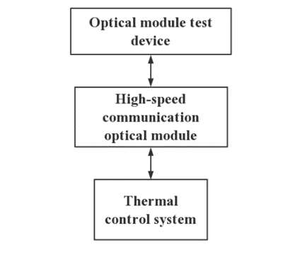
The functions of the high-speed communication optical module thermal control system in this paper are shown in Figure 2 below. On the basis of the following design requirements, the size of the thermal control system of the high-speed communication optical module is required to be less than 200mmx500mmx500mm, and the noise should be less than 65 decibels.
The function of TEC Cooling System
Design of DUT Thermoelectric Cooling Components
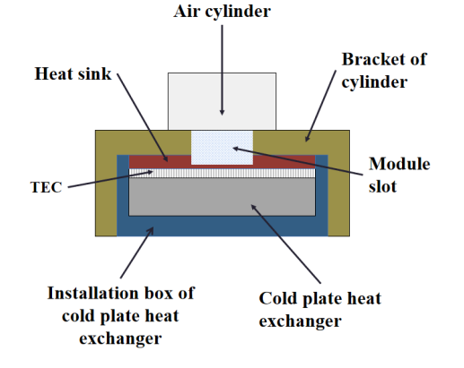
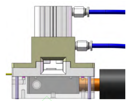
There are three types of optical module packages commonly used in the market today: QSFP-DD, QSFP28, and SFP+. There are three kinds of DUT test boards. Here, the thermoelectric cooling component of the QSFP-DD optical module is taken as an example. The DUT thermoelectric cooling component and the three-dimensional model are shown in the figure below.
The heat sink ensures uniform heat exchange between the optical module and the thermoelectric cooler, which can effectively reduce the total heat transfer resistance. Due to structural limitations, there are many connection points of thermoelectric cooling components, which will lead to heat leakage; the use of cylinder brackets and cold plate radiator installation boxes can effectively reduce heat leakage. In order to reduce the temperature difference between the two sides of the thermoelectric cooler and improve the cooling efficiency of the thermoelectric cooler, a liquid cooling solution is adopted.
The hot end of the thermoelectric cooler is directly in contact with the surface of the cold plate radiator, and the heat is brought into the TEC heat dissipation system through the flowing low-temperature water cooling liquid, and the heated water cooling liquid returns to the cold plate radiator for cooling The optical module performs heat exchange. It should be noted that the TEC needs to tightly adhere between the heat sink and the cold plate heat exchanger with thermal conductive silicone grease so that the TEC can fully contact them and facilitate heat conduction.
Thermoelectric refrigeration components at DUT
Package 3D model of Thermoelectric refrigeration components
Cold Plate Heat Exchanger Design
The structure of the cold plate heat exchanger should ensure that the cold plate can provide enough cooling capacity in the specified working environment so that the heat generated by the hot end of the thermoelectric cooler in the module can be dissipated in time. The heat transfer capacity of the cold plate must be guaranteed to meet the heat dissipation demand of 275W when the environment is at room temperature of 25°C. Although theoretically, a waterway with a square channel section has a larger contact area than a waterway with a circular channel section, due to cost considerations, the cold plate with a circular channel section was finally selected, and the processing between the water inlet and the water outlet into an S shape.
The material of the cold plate is red copper T2, and the material of the joint for cooling water is brass. The surface is nickel-plated as a whole to improve its strength and prevent oxidation. And the surface is finely ground to improve the surface smoothness. Since the water-cooling liquid needs to absorb heat from the hot end of the TEC when it passes through the water-cooling head, the material with a high volumetric specific heat capacity should be selected for the cold plate to ensure that its heat conduction efficiency is fast enough to transfer the heat absorbed from the hot end to the water-cooling liquid in time.
Design of Cold Plate Heat Exchanger in Heat Dissipation System
Considering the cost issue, the cold plate heat exchanger has the same parameters as the water cooling head designed in the DUT thermoelectric cooling assembly except for the length of 100 mm. The internal fluid flow velocity is simulated by Flow Simulation, which is realized by using the verified computational fluid dynamics (CFD) technology calculation. According to the fluid simulation results, the flow velocity of the fluid in the structure is basically less than 0.02m/s; That is, the waterway structure is not conducive to the circulation of liquid, which will affect the heat dissipation effect of the cold plate.
Comparison of temperature cycle efficiency between thermal control system and water cooler
According to the MSA multi-source agreement QSFP28 and QSFP-DD packaging mode, the power of high-speed communication optical modules is 7W and 14W respectively, but usually, manufacturers will use 5W and 12W as the factory standard of the module in order to reduce the power. In the MAS multi-source agreement, 1.5W is set as the power of SFP28, and the manufacturer will reduce the power to 0.9W when leaving the factory. Estimated in terms of power, as long as the thermal control system meets the temperature rise and fall requirements for a single QSFP-DD package-type optical module, then two QSFP28 package-type optical modules can be tested in parallel at the same time under the condition that the DUT test board specification remains unchanged. , 4 SFP28 optical modules, greatly improving the testing efficiency of optical modules.
Conclusion
According to the production and testing requirements of modern high-speed communication optical modules, this paper designs a thermal control system for high-speed communication optical modules and introduces the structure and working principle of the thermal control system. Then a DUT thermoelectric cooling assembly was designed and its cooling effect was verified using Flotherm. The heat dissipation system was designed and the internal wind path simulation was carried out. Finally, compare the heating and cooling efficiencies of the thermal control system and the water chiller.
The experimental results prove that the thermal control system basically meets the temperature control requirements for high-speed communication optical modules in commonly used packaging methods, and has the advantages of miniaturization, low noise, and zero vibration compared with water coolers. And the thermal control system can control the temperature rise and fall time of the optical module in the QSFP-DD packaging mode within 110s; the temperature rise and fall time of the optical module in the QSFP28 packaging mode can be controlled within 60s.
Compared with the temperature control efficiency of the water cooler for the optical module, the overall thermal control system is 10s slower than the water cooler, but the volume of the thermal control system is one-third of the water cooler and has zero vibration and low noise, which can meet the extreme temperature of the module The temperature control efficiency requirement of the test is suitable for the integrated test of the optical module function.


